This research was my bachelor thesis conducted under Professor Lin,Ta-Te.
It had also received a fellowship for undergraduate research from the Ministry of Science
and Technology.
In recent years, the widespread use of unmanned aerial vehicles (UAVs) in various fields has
been hampered by challenges in indoor navigation due to satellite signal masking. This
research focuses on developing an indoor autonomous navigation system for UAVs, utilizing a
Visual SLAM algorithm instead of traditional Wi-Fi-based triangulation. Built on ROS Noetic
with Ubuntu 20.04, our system employs RTAB-Map and ROS move_base for navigation, along with
YOLOv4 and Deep SORT for flower detection and counting. By addressing the limitations of
traditional methods, we aim to facilitate UAV applications in greenhouse operations with
enhanced precision and reduced technical barriers.
Introduction
With the rapid progress in science and technology, unmanned aerial vehicles (UAVs) find extensive applications across diverse sectors. In the mining industry, UAVs play a pivotal role in tasks such as 3D mapping of mine environments, ore control, rock discontinuity mapping, post-blast rock fragmentation measurements, and tailing stability monitoring. Similarly, in agriculture, UAVs are commonly utilized for efficient pesticide spraying over large areas. While modern UAVs rely on global positioning systems (GPS) for positioning and route planning, challenges arise in indoor environments due to signal masking, leading to localization deviations. Addressing this, the research focuses on developing an indoor autonomous navigation system for UAVs, aiming to create a simulation system for automatic mapping and route planning.
Approaches
> Overall System Archetecture
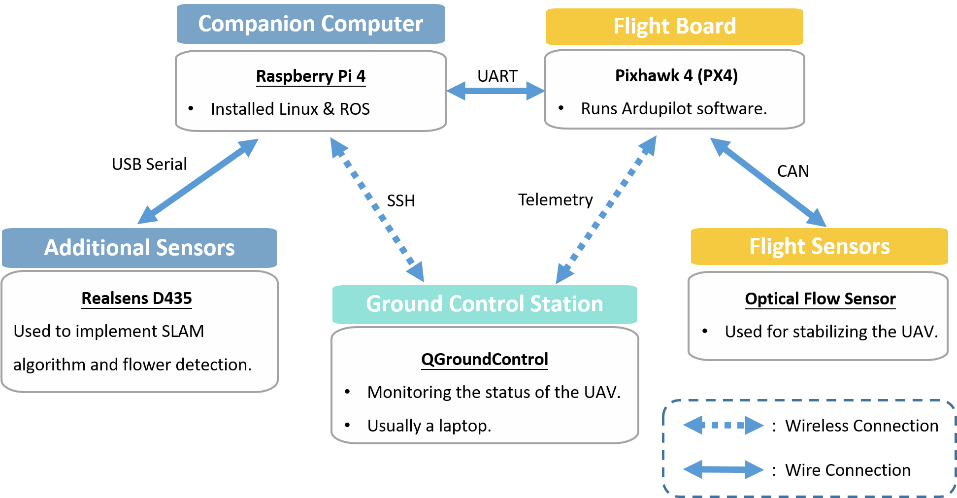
Figure 1. Overall system archetecture
The UAV system we had designed was composed of three main components:
1. Companion Computer: We used Raspberry Pi 4 as our companion computer.
A companion computer is used to reduce the computational load of the flight control unit.
2. Flight Control Unit(FCU)
The flight control unit is used to monitor and control the four rotors. The flight control board equipped on our UAV was
Pixhawk. Pixhawk is an open-sourced flight controller which contains built-in inertial measurement units (IMU).
3. Ground Control Station(GCS)
A ground control station(GCS) is typically a software application running on a ground-based computer that communicates
with the UAV through telemetry. It will monitor and display the real-time data and signals on the UAV. It can also be
used to control the UAV in flight by uploading new mission plan or commands.
> Navigation System
Traditional method of indoor navigation for UAVs is triangulation.
This method estimates the position of UAV based on the Wi-Fi signal strengths transmitted from different Wi-Fi routers.
Thus, multiple Wi-Fi devices is needed. The reason for not using triangulation in this study is that
this method requires multiple routers to be set up indoors
which not only increases the trouble for farmers to use but also raise the cost of installation and maintenance in the future.
Therefore, compared with traditional methods of indoor navigation, we use Visual SLAM algorithm for UAV autonomous navigation in this research.
The VSLAM system used in this research is RTAB-Map.
The whole navigation system can be roughly separated into three parts: mapping, localization and route planning. Both
mapping and localization would be done by RTAB-Map and route planning would be implemented by move_base. Move_base is a
ROS package that provides an implementation of an action that will let the robot attempt to reach a given goal in the
world with its mobile base.
The map of the whole environment would be constructed by conducting a guidance flight at the first flight. RTAB-Map will
take the RGB-D images, IMU data from the flight control unit, and camera information as input to calculate the visual
odometry. It will then generate a 2D occupancy grid map and the TF (transform of the robot from /map to /odom). The two
data are then sent back to the flight controller in order to let the controller know the position of the UAV. These two
data would also be used by the move_base package in order to plan route to reach the target position.
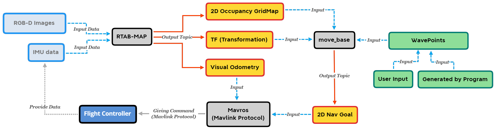
Figure 2. Block diagram of the whole system
> Application: Flower Counting System
In addition, deep learning was also applied to this research in order to provide a simple application with this system. Our training model was to identify and calculate the amount of the flowers of eustoma farms. Flower growers are often concerned about how many flowers grown in the greenhouse since this is highly related to their income. Thus, a flower counting system is implemented using YOLOv4 and Deep Sort. Figure 3. shows the system archetecture of the flower counting system.
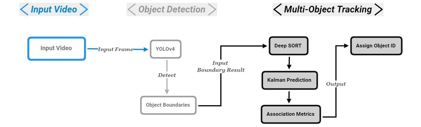
Figure 3. Flower counting system archetecture with YOLOv4 and Deep Sort
Results
The UAV model we were using in the simulation is provided by PX4-Autopilot on GitHub and the greenhouse model was designed referring to the Eustoma farm situated in Changhua County. Once the UAV is armed, we can control our UAV through Rviz, a 3D visualization tool in ROS. We can add waypoints to the map by clicking on the control panel (Figure 12). The UAV will then navigate to the designated location if the goal is reachable. This action is done by adding goals to move_base service and the service will complete route planning. While moving the UAV around, RTAB-Map is also publishing the location and poses of the UAV and updating maps to provide sufficient navigation information to move_base service. Figure 4. was the mapping result of the simulation environment. We had also tested our system on our UAVs in the greenhouse. Figure 5. was the mapping result of a single block of the actual eustoma farm.
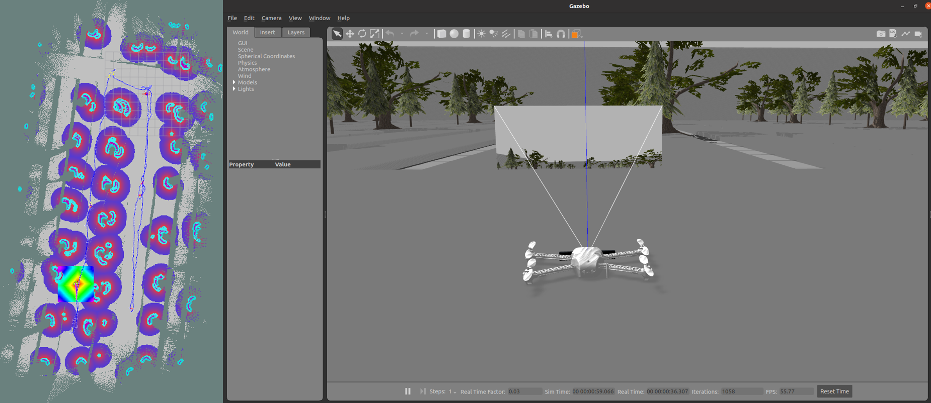
Figure 4. Mapping result in simulation using Gazebo and Rviz
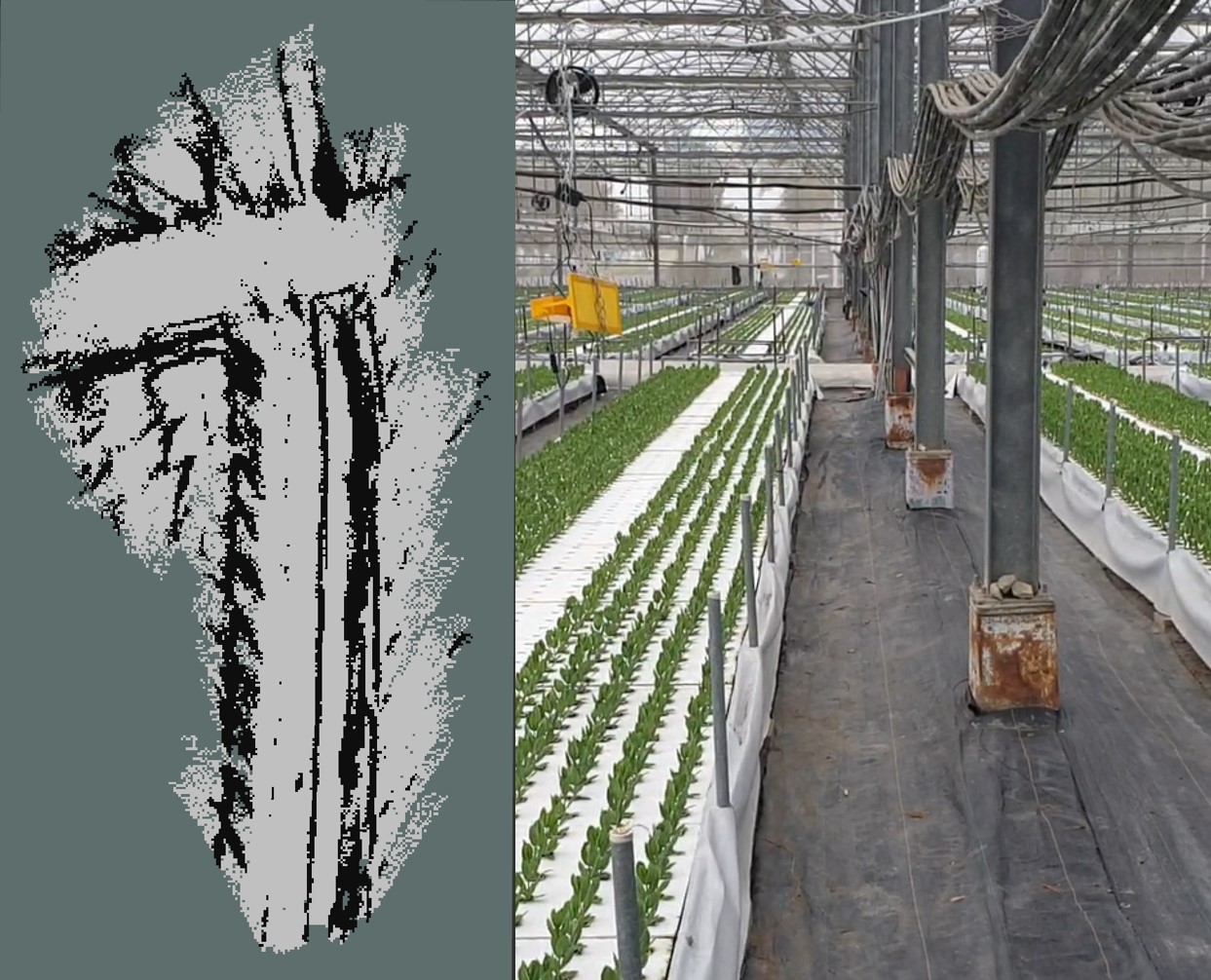
Figure 5. Mapping result in reality
Pictures of the flowers were taken from the camera equipped on the UAV. These pictures were then used for our model
training so that it could be used for flower detection in the future.
We collected 179 pictures taken from the greenhouse and approximately 20 to 80 flowers on average are in each picture.
After training from the collected images from the farm, our YOLO model can achieve F1 score 0.968, representing that the
model we had trained can identify the eustoma flowers accurately.
Figure 6 was our flower counting system combined with YOLOv4 and Deep SORT. We first recorded the video through the
Realsense camera equipped on the UAV and then this video was input into our flower detecting system. While detected a
new flower in the frame, Deep SORT would then start figuring the detected flower’s ID. If the flower was new detected in
the frame, Deep SORT would assign a new ID to it, otherwise the flower would obtain its original ID assigned while it
was first detected. We could then use this ID to count the flower amount of the whole video.
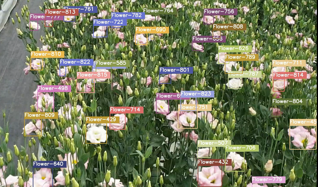
Figure 6. Flower counting system with YOLOv4 and Deep SORT
Publication
Bachelor Thesis
https://drive.google.com/file/d/12jyPmkv3QKi3j0LRHbomRwebeSe-pRvo/view?usp=sharing